Software introduction
In this lab, we are using Pix4DMapper first time. According to its website, Pix4DMapper is a photogrammetry software designed for professional drone mapping. Given the fact that this software is part of the broader Pix4D products, pay careful attention to the name of the program that you open. When flying a mission, consider what needs to be imaged. For example, in general, a mission flown over a road going through a cornfield will require a smaller percentage of imagery overlap compared to a mission flown over a uniform field/snow. After referring to the Pix4D manual under the 'Ideal Image Acquisition Plan', it appears that you need at least 70% overlap 80% sidelap for less complicated projects and a minimum of 80% overlap 80% sidelap for larger projects.
Although the processing times can be compromised (depending on the kind of hardware available) Pix4D can and will process multiple flights as long as the key-points are close enough to merge among one another, the the altitude is the same, and the environmental factors are the same. In additio,n pix4D can and will process oblique images as long multiple flights with multiple altitudes with multiple camera angles are taken. Referring to the online Pix4D manual, it appears GCPs be used especially if nadir data is available. Although GCPs aren't absolutely necessary for Pix4D, they are highly recommended when mapping items such as rivers, roads, and railways.
One other mentionable feature of Pix4D is Rapid Check. Rapid Check is a program option that enables a user to generate a quality report quickly in case the user wants to cross-reference data before processing it thoroughly. To better understand how to use the software, I have created a tutorial for processing example data of a UAV that has flown over a house. Before referring to the steps, it is important to note that this procedure is Purdue specific, and before setting up the program, you must have access to a computer in the AT 319 lab, as well as the given folder in figure 1.
 |
| Figure 1:Given Folder tor this Tutorial |
Software Tutorial
- Access Class data folder shown in Figure 1
- Copy Lab4and5_ArcProPix4D into Temp folder of C drive
- Click on Lab4and5_ArcProPix4D
- go to flights folder
- click Flight1_Nadir
- You will now see a series of pictures, right click on one of the pictures
- go to properties
- go to details
- Note the details such as the camera sensor and coordinates
- Open up Pix4Dmapper
- login with provided username and password
- On the home Screen, similar to the image on Figure 2 click create new project
- Remember to logout when you are done otherwise we risk loosing money running the system)
 |
| Figure 2: Pix4D Home Screen |
- A new screen will appear, now click browse.
- Navigate to the temp folder mentioned in step 2
- Name the file by including metadata such as the date, the sensor, the altitude flown, and whether or not gcps were included.
- Click Next
- Click Add Images
- Click Flight1_Nadir, images similar to Figure 3 will appear
- Click Open. All the images will now appear in a list.
 |
| Figure 3: Unstiched Images taken from UAV |
- Click next, you will now see a chart including items such as images, groups, altitude.
- Click edit and switch shutter model to Linear Rolling.
- Click next, be sure to reference the output system.
- Click next, you will now be on the Processing Options Template Window
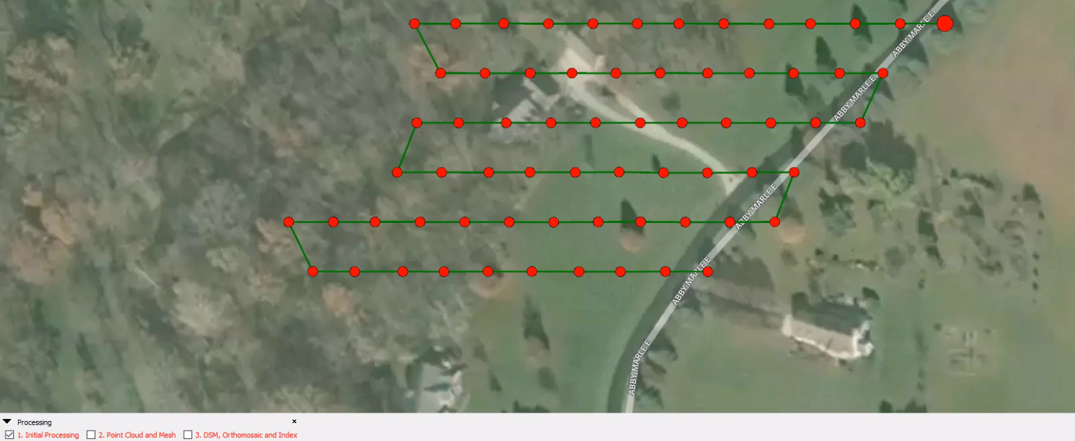
- Click 3D Maps, and click Finish. A flight path similar to Figure 4 will now appear.
- Referring to the bottom left corner of Figure 4, make sure the boxes for both point cloud and mesh and DSM, Orthomosaic and Index are unchecked
 |
| Figure 4: Flight Path of UAV |
- Click on Processing Options
- A window will appear
- Check both point cloud and mesh
- Check DSM, Orthomosaic and Index
- On the DSM, Orthomosaic and Index, switch the method to triangulation
- Check GeoTiff
- Check Google Maps Tiles and KML
- Click on Additional Outputs Check SHP
- Set Elevation to 0.5m
- Set the Minimum Line size to 100
- Click Ok you will now be back at the same picture scene in Figure 4
- Once again, make sure Initial Processing is the only thing that is checked
- Now click Start, once the initial processing is done, a quality report will appear as seen in Figure 5
 |
| Figure 5: Quality Report |
- Note items such as the summary, Quality check, the Preview, Calibration, etc..
- Click Close, you are now ready to process your data
- Uncheck Initial Processing
- Uncheck Point Cloud and Mesh
- Uncheck DSM, Orthomosaic and Index
- Click Start, when processing is complete, you will now have your initial Data point cloud processed similar to Figure 6
- On the layers window shown in figure 6, check off point clouds
- Note the difference in texture
- Turn off Point clouds and check Triangle Meshes
- Note the difference in texture as shown in figure 6 and 7
 |
| Figure 6: Point Cloud Without Triangle Mesh |
 |
| Figure 7: Point Cloud With Triangle Mesh |
At this point (and no I'm not talking about the cloud) the project is complete. In the lab for next week, we will add the ground control points. For your pleasure, take a look at the following link for a more detailed view:
https://www.youtube.com/watch?v=A8OVPAcwplI&feature=youtu.be
Software Results
As seen inf Figure 8, Pix4D's files and folders are organized in a series of folders and subfolders. For clarity, the folders are labeled with two black and white rectangles, and the saved file is the rhombus with the Pix4D symbol written in green.
 |
| Figure 8: Organization of Pix4D Files and Folders |
When taking a closer look at the quality report referenced in the Tutorial, I have included a table with the processing times and statistics and statistics in Figure 9.
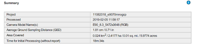 |
| Figure 9: Table With Processing Times and Statistics |
In Figure 10, a total of 67 images were used and one image was rejected
 |
Figure 10: Used vs Rejected Images
In figure 11, are the overlap results from the quality report. As you can see fewer images are overlapped on the edges of the image. Although results may vary, this could be due to the UAV turning, the UAV sensor being able to orient further images, or be due to the terrain being more difficult to stitch together.
|
 |
| Figure 11: Overlap Results |
In Figure 12 is a map showing the Orthomosaic that was first stiched in Pix4D and then transferred to Arc Pro. In the image is an overhead view of a house in northern Lafayette Indiana.
 |
Figure 12: Orthomosaic of house in Lafayette Indiana
In Figure 13, is a Digital Surface Model of the same image in Figure 12 showing some of the terrain features. As you can see in some areas, the data was not stitched properly. This could be due to the fact that the vegetation in the image caused the data to error. Nevertheless, you can see the differences in elevation based on the color when referring to the map.
|
 |
| Figure 13: Digital Surface Model of Figure 12 |
Conclusions
During this lab, I learned how to create an Orthomosaic from Pix4D mapper and then interpret it using Arc Gis Pro.If done correctly, Pix4D can provide a quick and professional way to process data. If done incorrectly, Pix4D could still process the data, but the results can vary tremendously. Because of this, here are many considerations that one must ponder when deciding how they should go about processing data.
One of the several considerations one must be familar with is knowing how to define global and rollong shuter. According to Pix4D's website, global shutter exposes all of the pixels of the sensor at one time, whereas a rolling shutter exposes each pixel row of the sensor at slightly different points in time. For your reference, Figure 14 provides a visual representation with the left image representing global shutter and right image representing the rolling shutter. If a user does not remember to consider that when using Pix4D, data processing could result in lots of errors.
In addition to being exposed to several new parameters that must be considered when using Pix4D, I also learned that the software can process data rather quickly depending on the nature of the project. Given the fact that this is my first time building an Orthomosaic I will have more specific experiences about it in later labs.
 |
| Figure 14 Global vs Rolling Shutter |


No comments:
Post a Comment