Lab Description
Perhaps one of the most lengthy labs yet, this project has multiple parts and is mainly about the extensive planning and crew resource management procedures that are essential to complex unmanned aircraft systems. Specifically, myself and small group are going to learn the basic fundamentals of using the C- Astral Unmanned Aerial System. For clarity, the C-astral UAS consists of the UAV, the the ground control station, the catapult, and the parachute. Special emphasis for this lab is placed on the pre-planing of this UAS and below are the objectives that will be covered:- Gain a basic understanding of mission planning essentials
- Understand how mission planning and pre-flight checks are integrated
- Learn how to use C-Astral Mission Planning software
Table Of Contents
Part 1-----------------------------------------------------------Overview of C-Astral UAS
Part 2-----------------------------------------------------------Un-boxing the C-Astral
Part 3-----------------------------------------------------------C-Astral UAS Mission Planning
Part 4-----------------------------------------------------------Overview of the C-Astral Checklists
Part 5-----------------------------------------------------------Office Checklist
Part 6-----------------------------------------------------------Packing Checklist
Part 7-----------------------------------------------------------Pre-flight Checklist
Part 8-----------------------------------------------------------C-Astral Software
Part 9-----------------------------------------------------------C-Astral Software Demonstration
Part10----------------------------------------------------------Conclusion
Part 1: Overview of C-Astral UAS
The C-Astral Bramor UAS is a relatively complex system with nearly fully autonomous capability and offers multi-spectral, visible light, and thermal remote sensing in one package. Based out of Slovenia, this system is capable of acquiring data for surveying and provides fast and precise results. Although it can greatly outperform most fix winged UAS systems, it must carefully be operated in accordance with the United States FAA regulations. Shown in Figure 1, is the Bramor ppX with its catapult and Ground Control Station Unit.
Taken from the C-Astral User Manuel, "the system can be safely operated by one operator/pilot in command, but a crew of two is desirable for situational awareness purposes and where regulations require so". Therefore in the Part 4, myself and a small team of other UAS students engaged in a 1-hour crew resource management activity where we went through non flight procedures only! As one of my first extensive large scale UAS checklist, there will be many more improved blog posts in future posts.
Taken from the C-Astral User Manuel, "the system can be safely operated by one operator/pilot in command, but a crew of two is desirable for situational awareness purposes and where regulations require so". Therefore in the Part 4, myself and a small team of other UAS students engaged in a 1-hour crew resource management activity where we went through non flight procedures only! As one of my first extensive large scale UAS checklist, there will be many more improved blog posts in future posts.
 |
| Figure 1: C-Astral Bramor ppX and its Catapult |
Part 2: Un-boxing the C-Astral
In this class, we have available a C-Astral ppx which we will be using for future missions. Shown in Figure 2, are two C-Asteral equipment cases. Case 1 has the C-Asteral UAS, its air-frame, and its and Ground Control Station. Case 2 has the catapult equipment.

Figure 2: Case 1 and Case 2
Combined together, the C-Asteral is transported with Case 1 on the top, and Case 2 on the bottom shown in Figure 3.

Figure 3:C-Astral Cases for Transportation
Shown in Figure 4, is Case 1 opened. Below Figure 4, you will see the a description of each item listed excluding the body of Bramor itself.

Figure 4: Case 1 Opened
1.Batteries
2.Cables
3.Backup Propellers
4.Parachute
5.Septentrio GNSS Ground Control Station
6.Camera lense Cleaner
7. ADS-B-S-Mode Transponder- connects to ground control station
8.Wing Tape
9.Tools/ Documentation/Manuals
Within the lid of Case 1, a sub-compartment between the Bramor UAS a hosts the two large white wings and the two small winglets shown in Figure 5.

Figure 5: Bramor Wings and Winglets
Referring to Case 2, is the folded catapult equipment shown in Figure 6.

Figure 6: Folded Catapult
Referring to Figure 7, is a diagram of the elastic catapult when set up taken from the the C-Asteral help manual. Below Figure 7 is a description of items that should be looked over during the pre-flight checklist.

Figure 7: Elastic Catapult Diagram
- Catapult legs
- Safety lock
- Catapult Pulley
- Catapult Rail
- U shackle
- Elastics
- Winch rope
- Middle hinge
- Middle lock
- Rubber and Sticker
- Breaking rope
- Catapult carbon seating
- Trolley
- Trolley wheel
- Safety Pin
- Catapult release
- Winch handle
- Leg plate
- Winch
Part 3: C-Astral UAS Mission Planning
 |
| Figure 2: Case 1 and Case 2 |
 |
| Figure 3:C-Astral Cases for Transportation |
 |
| Figure 4: Case 1 Opened |
2.Cables
3.Backup Propellers
4.Parachute
5.Septentrio GNSS Ground Control Station
6.Camera lense Cleaner
7. ADS-B-S-Mode Transponder- connects to ground control station
8.Wing Tape
9.Tools/ Documentation/Manuals
Within the lid of Case 1, a sub-compartment between the Bramor UAS a hosts the two large white wings and the two small winglets shown in Figure 5.
 |
| Figure 5: Bramor Wings and Winglets |
Referring to Case 2, is the folded catapult equipment shown in Figure 6.
 |
| Figure 6: Folded Catapult |
Referring to Figure 7, is a diagram of the elastic catapult when set up taken from the the C-Asteral help manual. Below Figure 7 is a description of items that should be looked over during the pre-flight checklist.
 |
Figure 7: Elastic Catapult Diagram
|
Part 3: C-Astral UAS Mission Planning
Within this topic, there are multiple subcategories that I could spend days working on, but since I am a college student enrolled in other classes, consider this list a skeleton of items to consider. Note, these items are in no particular order and it is up to you to determine whether or not your procedures are inclusive enough.
- Know your UAS- although this sounds obvious, certain UAS perform better in certain missions. To maximize the performance of a UAS, this will greatly depend on the experience of the pilot, robust pre mission planning, and how much effort you put into to knowing airspace, regulations, and weather. Shown in Figure 2, are two charts displaying the C-Astral's technical and flight parameter data. Since I know that the flight will be pre-programmed and autonomous, I have to ensure that the area I am flying in can accommodate those needs. If not, I will need to use a different UAS. Lastly, this UAS requires a parachute to land therefore one must have to know how to fold a parachute in order to not to destroy the aircraft upon a completed mission!

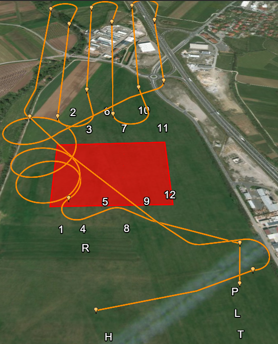
Figure 8: Technical data and flight Parameters of C-Astral UAS - Know your study site- Figure 2 depicts a simulation screenshot of the C-Asteral in a field, Symbolized with a fix winged UAV Icon, the C-Asteral is in its Home position, the circle directly North of it is the Take off Icon. The triangle with the numbers are the Waypoints, the circle with the capital R is the Rally Point, the P is the Parachute Point and the L with the purple spot is the estimated Landing Point.

Figure 9: Study Site Icons


Furthermore, knowing your study site can help determine places to set up items such as:
- Ground Control Stations
- Ground Control Points
- Possible Obstructions
- Tall trees
- Buildings
- Water
- Power lines
- Visual Observers
- Amount needed to maintain situational awareness
- Where each observer will be placed
- Take Off points
- Way-points
- Landing Points
- Emergency Landing Locations
- Cell Signal- while in remote locations, consider who is going to have access to internet, let alone real-time weather and appropriate mobile applications such as B4UFLY, LAANC, etc.., On the other-hand, as depicted in Figure 3, signal is not always reliable.
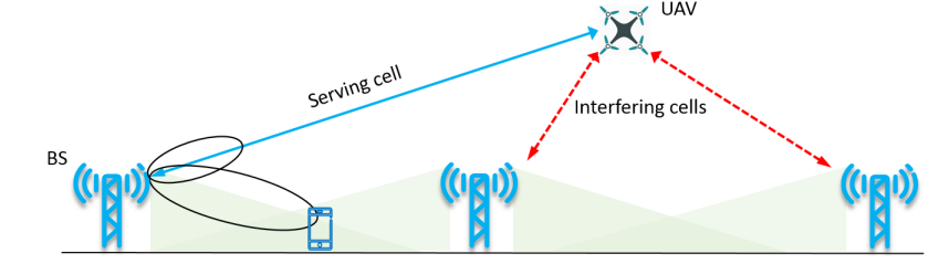 |
| Figure 10: Challenges of Cell Phone Signal |
- Crowd Considerations- Unless exempted from current FAA regulations, CFR Part 107.39 operations explicitly prohibit the operation of a UAS over people who are not participating.
- Know the vegetation
- Site accessibility
- Know the Terrain
- MSL vs AGL
- Look at Figure 2 for possible Anthropogenic obstacles and features- although this appears as an ideal area to fly, how much walking is required to set up the UAS? Could be there be power lines on the perimeter of each road? I this area large enough for a catapult launch? Will the visual observers be challenged with varying terrain to keep eyes on the UAS at all times? These are just a few questions you should be asking yourself before you get to the field.
- Draw out several possible mission plans-
- Use geospatial data available such as the data in Figure 11
- Check weather- The location for this hypothetical flight is near Gradisce pri Vipavi, Slovenia. Taken from google today, Figure 11 depicts the 5 day forecast. If you were to fly, which day would you choose? When determining this, do not limit yourself to just googling the weather forecast like I did. For example, for Monday although it appears that is going to rein all day, there is a significantly less chance of this likelihood at 8:00am.Some other items that you should consider when looking up weather include:
- Daylight
- Wind speed/wind direction
- Visibility
- Temperature
- Humidity
- Cloud Coverage
- Real time radar
- Dew Point
- Equipment- In this scenario, the C-Astral Case weighs over 145 lbs and despite having handles and wheels, it cannot be carried by one person. In addition, the size of the case will make fitting it in a small car difficult so the vehicle you use to safely transport the UAS must be considered. Lastly, when you are going out in a remote area, consider the fact that there might be poor access roads to your operating site. Therefore you might have to Figure out how you are going to safely transport the system through forested areas, up steep hills, across creeks, or anywhere that cant be accessed by vehicle.
- Batteries Charged for all electronics- If you are going to spend hours on the field in a remote area far from adequate resources, you need to make sure that your necessary batteries are charged. The suggested items below can include but is not limited to:
- Cell Phone
- mifi source
- Transmitter
- UAV batteries
- Ground Control System Batteries
- Camera Batteries
- Sensor Batteries
- A generator
 |
| Figure 11:Example of Available Geospatial Data |
Part 4: Overview of C-Astral Checklists
In Figure, is the C-Astral Bramor ppX Checklist handbook. Within this handbook, there are several sub checklists that myself and 3 other people went over. The specific subsections that will be covered are the Office Checklist, the Packing Checklist, and the Preflight Checklist In total, 122 steps are listed to check but not all the steps are entirely clear. To ensure that we properly understood the items we were looking over, there were about about 20 other steps that we needed to make sure we covered. As mentioned before, there is not enough time to list every step however below are the sections and the amount of steps per section that we went over to give you an idea of our process.
Part 5: Office Checklist (Steps 1-9)
This can be within or in addition your overall mission pre-planing therefore most of this consists of taking an inventory of and checking all the items found in Steps 1-122. Nevertheless consider this a separate checklist because pre-planning can take months (depending on the mission), where as an office checklist could be within 24 hours of a flight.
In an effort to enact a mission, we assigned a pilot in command, a co-pilot, a ground a visual observer and an equipment manager. For this specific activity I was the co-pilot and my role was to oversee mission planning, and the checklist while communicating with the pilot in command. Below, in Figure 12, is a diagram I created which lists our roles for the hypothetical mission.
 |
| Figure 12: Crew Resource Management Diagram |
- Batteries for all electronic devices
- SD card
- Tools
- Elevation map
- Ensuring that your case is free from damage and open/locks correctly
Part 6: Packing Checklist (Steps 9-34)
This consists of making sure that each item within both cases are carefully looked at. Important items for the packing checklist are broken down by case number include but are not limited to:
- Case 1
- Wings
- Winglets
- Parachutes
- The parachute folding tool
- Parachute safety pin
- parachute hatch
- propellers
- Ground control station
- electrical tape
- Tablet
- tablet charger
- wing joiners
- Mairframe hatch
- Pitot Cover
- USB Key
- Appropriate chargers
- Case 2
- Catapult
- Elastics
Part 7: Pre-flight Checklist (Steps 34-122)
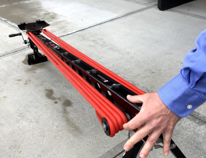
Within this section nearly 30 of the steps involved setting up the catapult as seen in Figure 13 . Notice the of size of the catapult with respect to the equipment manager, our professor and the visual observer. Since out field demonstration didn' involving any flying, we were able to set up the UAS right in front of KLAF airport.
Something that confused us during the process was having to carefully stretch the bungees shown in Figure 14.
 |
| Figure 13: Setting up the Catapult |
 |
| Figure 14: Securing the Bungees of the Catapult |
 |
| Figure 15: The Catapult facing the Headwind |
 |
| Figure 16: What not to do when holding a Catapult |
 |
| Figure 17: How to Properly Hold the Catapult |
While the equipment manager and the visual observer set up the catapult, myself and the pilot in command began programming the C-Astral for a hypothetical mission shown in Figure
 |
| Figure 18: Setting up the Hypothetical Mission on the Ground Control Station Tablet |
 |
| Figure 19: Assembling the Airframe to the Catapult |
 |
| Figure 20: Attaching the Propeller to the Bramor |
 |
| Figure 21: Pitot Static Tube |
 |
| Video: Parachute Installation |
 |
| Figure 22: Hypothetical Launch of Bramor UAS |
Part 8: C-Asteral Software
In Figure 23, is a screenshot of the home screen at a hypothetical field in Bosnia. Below is a description of each of the items in the numbered boxes.
 |
| Figure 23: Screenshot wirh Labled Boxes |
Box 1
- The Help Section-Indicated by the ? click (on) this and it will open up an entire subsection that you can refer to for questions you may have as shown in Figure 24

Figure: 24: The Help Section Window - The Map Icon-Changes the map so that you can see other items such as cities, rivers, and other topography more clearly
- The Attitude Indicator-a flight instrument that informs the pilot of the aircraft orientation relative to Earth's horizon, and gives an immediate indication of the smallest orientation change

Box 2
- Battery Life, Communications, the Global Navigation Satellite System Receiver gauges
- Altitude Above Ground Level, Airspeed inidcatior, Climb, Throttle gauges
- Wind
- The Connection Status-Indicates when the Bramor is connected to the ground control station
- Simulation Status
Box 3
- Click (on) Settings indicated by the gear icon and a small window will appear shown in Figure 26

Figure 26: Settings Window - Minimize, expand and close buttons are next to the settings button
- Metadata showing the elevation, distance duration etc.., is below the buttons

Box 4
- Safe mode
- Manual mode
- Take off mode
Box 5
- Map- Click (on) this to enable different features for mission options shown in Figure 27

Figure 27: Mission Options - Mission Settings- when clicked on Figure 28, a window similar to Figure will appear. In this scenario altitude is set to 200m which would not work in a current part 107 operation. Nevertheless, speed is critical to the aircraft's flight, and overlap and sidelap are crucial for photogrammetry.

Figure 28: Mission Settings - Draw- when clicked on, a window similar to Figure 29 will appear. This is how you create a flight path and waypoints.

Figure 29: Draw tool - Hide, delete, clear, and undo/redo buttons all help edit waypoints


Box 6
- Sensor Calibration
- Waypoint Upload
- Parachute Pop
Box 7
- Upload mission indicated by the folder
- Waypoint status- Click (on) the arrow like icon and a chart similar to Figure 30 will appear

Figure 30: Waypoint Chart - Save Icon, saves the mission

- Camera Controls
- View/Edit Photos
- Auto Camera
- Zoom
Part 9: C-Astral Software Demonstration
In this section, I have completed simulated missions for three locations. Location 1, the Bramor test site shown in Figure 31 . Location 2. the County Amphitheatre Park in West Lafayette shown in Figure 33 , and Location 3, the Thorton Quarry Shown in Figure 35 .
Throughout this demonstration, was tasked with addressing the following:
As you can see in Figure 34, there is significantly more planning that needs to be done compared to Location 1. For example, is the field north of the amphitheater large enough to serve as the Bramor's home position. In addition, are the trees too tall for an altitude of 50 meters? Lastly, if our mission is to gather adequate photos of the amphitheater parking lot, what ideal altitude can we fly at in accordance with FAA Part 107? With a set altitude of 50 meters, the mission flew successfully, but would this flight path be safe in real life?
In Figure 35, is a comparison of the 3D flight path vs the 2D flight path from above. Notice how much more tight and complex this mission was compared to the mission on the test site.
Location 3
Perhaps the most changeling of the locations is Thorton Quarry located in Illinois. Shown in the satellite image in Figure 36, there are multiple elevation differences, roads, and a neighborhood in the bottom right hand corner.
Shown in Figure 37 was my first flight path draft. Notice all the elevation hazards in orange circles. If the UAS were to fly here, it would crash. For this mission, I also flew it on the side of the road shown on the left. In the left side of Figure 37, is the corrected flight with an adjusted altitude of 100 meters, notice how much farther from the road the Bramor had to be in order to safely fly.
Shown in the left side of Figure 38 , is the overhead view of the Bramour on its flight successfully surveying the Quary. Shown on the right side is its 3D model.
In this section, I have completed simulated missions for three locations. Location 1, the Bramor test site shown in Figure 31 . Location 2. the County Amphitheatre Park in West Lafayette shown in Figure 33 , and Location 3, the Thorton Quarry Shown in Figure 35 .
 |
| Figure 31: Location 1 |
- Experiment with altitudes, as well as relative and absolute heights
- Take note at how mission orientation relates to terrain issues
- Draw a corridor mission along a linear feature such as a road in the vicinity
Similar to Figure 28, I changed the speed and the altitude at the highest settings to see that kind of overlap would occur. In Figure 32, is an overhead view of the the first simulated mission. Below it are some items that help us understand what the Bramor did. The simulated mission was successful.
Within the purple box is the area that the Bramor covered
 |
| Figure 32: Aerial View of Flight Path for Location 1 |
- The clear boxes within the purple box are the photos the Bramor captured
- The orange diagonal lines are the flight path to the way points
- At the moment of this screenshot, the Bramor was heading to waypoint 8
In Figure 33, is the 3D view of Location 1 and its flight path. Below Figure 32 are more items of importance.
 |
| Figure 33: 3D View of Flight Path for Location 1 |
- H stands for home
- R stands for rally point
- P stands for parachute deployment Point
- L stands for Loiter
- The numbers are the order the Bramor flew in
- The Red box is the area the Bramor covered
As you can see in Figure 34, there is significantly more planning that needs to be done compared to Location 1. For example, is the field north of the amphitheater large enough to serve as the Bramor's home position. In addition, are the trees too tall for an altitude of 50 meters? Lastly, if our mission is to gather adequate photos of the amphitheater parking lot, what ideal altitude can we fly at in accordance with FAA Part 107? With a set altitude of 50 meters, the mission flew successfully, but would this flight path be safe in real life?
 |
| Figure 34: Satellite View of Amphitheater Parling lot |
 |
| Figure 35: 2D vs 3D Flight Path Comparisons for Location 2 |
Location 3
Perhaps the most changeling of the locations is Thorton Quarry located in Illinois. Shown in the satellite image in Figure 36, there are multiple elevation differences, roads, and a neighborhood in the bottom right hand corner.
 |
| Figure 35: Thorton Quarry Satellite Image |
 |
| Figure 37: Flight Draft That would Result in Accident |
 |
| Figure 38: 2D vs 3D Flight Path Comparisons for Location 3 |
Part 10: Conclusion
As stated before, since the Bramor is autonomous the second you release it from the catapult, this UAS platform can require extensive preplanning in order to ensure a safe and efficient mission. Although every aspect of preplanning is important, the pre-flight check is perhaps the most important because crew resource management determines whether or not the Bramor will produce stunning cost effective deliverables, or a stunning expensive hole in the ground. Although people are complacent with fallowing the traditional checklists that are given to them, professionals that want to minimize the likelihood of an accident will often add extra more specific steps in order to ensure that everyone is aware of themselves, the UAS system, the mission, and the environment.
More importantly, as demonstrated by these simulations, UAS missions can vary tremendously. Therefore, having a constant awareness for safety and being able to address potential hazards early could save you a UAV, a lawsuit, or even a life in the long run. In future labs, you will see more demonstrations of the Bramor ppX and how we will operate it as professionals in the field. As UAS relates to the client, the operator, and the national Airspace System, imagine having both the opportunity and responsibility to manage all three aspects let alone the the aircraft and all of its components.
More importantly, as demonstrated by these simulations, UAS missions can vary tremendously. Therefore, having a constant awareness for safety and being able to address potential hazards early could save you a UAV, a lawsuit, or even a life in the long run. In future labs, you will see more demonstrations of the Bramor ppX and how we will operate it as professionals in the field. As UAS relates to the client, the operator, and the national Airspace System, imagine having both the opportunity and responsibility to manage all three aspects let alone the the aircraft and all of its components.
No comments:
Post a Comment