Saturday, May 18, 2019

Flying In Forest Park St Louis Missouri

This weekend, I was given an opportunity to fly a DJI Phantom 4 PRO Version 2.0 and its accessories shown in Figure 1. To better prepare for future missions using this system, I plan to spend time reviewing the pref-light checklists, the operating procedures, and the flight system's characteristics. Shown below is a table of contents emphasizing the UAS system, and my mission planning process for the first flight.

Table of Contents
Part 1----------------------------------------------------------------------------------------------------Phantom 4 V2 Overview
Part 2----------------------------------------------------------------------------------------------------Location Considerations
Part 3----------------------------------------------------------------------------------------------------Weather Considerations 
Part 4----------------------------------------------------------------------------------------------------Office  Checklist
Part 5----------------------------------------------------------------------------------------------------On the Field Preflight Checklist
Part 6----------------------------------------------------------------------------------------------------UAS Mission

Part 1: Phantom 4 Pro V2 Overview
The Dà-Jiāng Innovations (DJI) Phantom 4 PRO V2.0 is a relatively versatile UAV that can be used for amateur, commercial, and hobbyist use. Shown in Figure 1 is the assembled version of the UAV, its gimbal, and its 20 megapixel camera attached. Similar to other DJI products, flight time for this system is "approximately 30 minutes" when referring to its specs. Although it's possible that the UAV could last in the sky 30 minutes, the mission parameters, its payload, and weather conditions can greatly reduce the advertised time.
Figure 1: DJI Phantom 4 Pro Version 2
Perhaps surprising to some, this system is no longer being produced by DJI .This is surprising because the series was cancelled with very little warning, so if someone wanted to purchase the UAV or its accessories, they will have to now buy it from a non DJI vendor. Shown in Figure 2 is an inventory of important items that are within the borrowed transport case:
  1. Camera Wipes and Lanyard
  2. Instructions for the UAS, Apple iPad, and iPad visor
  3. Transmitter
  4.  UAV
  5. Memory card box, gimbal protector
  6. Propellers
  7. Batteries
  8. USB cables for the tablet and UAV
Figure 2: Opened UAS Transport Case
Part 2: Location Considerations
Shown in Figure 3 is the location of my first mission with this system. By looking at the image, I was able to determine that there were not a lot of physical hazards aside from the trees surrounding the perimeters of the fields. Once I determined that this location has minimal physical hazards, I then refereed to Airmap.com to see what airspace hazards I might encounter. 
Figure 3: Satellite Image of Local Park
Shown in Figure 4 is the planned flight's location and its proximity to Saint Louis International Airport. Since the outer ring of the airspace is roughly 10 miles form where I wanted to fly, I did not need to consult the FAA LAANC system before the mission. Furthermore, I refereed to skyvector, and  UAV Coach.com where I learned that this location was in Class G Uncontrolled Airspace. Despite being in uncontrolled airspace, it is extremely important to note that helicopters are known to fly in the area and that flight over pedestrians is not allowed. 
Figure 4: Flight Location in Proximity to KSTL

Part 3: Weather Considerations
Although I had the entire day Sunday to use the UAS, the weather did not cooperate. The biggest factor that prevented me from flying was the wind. According to a custom checklist provided in the case, it was not recommended that I fly the UAV if the winds exceeded 25mph. At my first glance of the weather forecast, I looked at the image shown in Figure 5. Although the wind in Sunday's forecast was less than the wind threshold mentioned, this did not account for wind gusts. Furthermore, according to the UAVs specs, the maximum wind "resistance" is 10 m/s or approximately 22 miles per hour. 
Figure 5: Google's Forecast
Shown in Figure 6 is the METAR for Saint Louis International Airport. Although data collected from the METAR is roughly 10 miles away from the flight's location, wind gusts are 31 miles per hour which exceeds the recommenced practice of the checklist and the specs. As a result, I post-poned the flight to a later time. I then decided that I would attempt a flight around 6:30pm when the wind died down. However, civil twilight ended around 8pm which meant that I would have to operate from 7:00pm to 7:30pm to stay in line with FAA Part 107 regulations and by the time I set the system up, I determined that I was rushing myself and made the decision to cancel the mission so that I can go over everything more slowly.
Figure 6: Sunday METAR Conditions
Part 4: Office Checklist 
A few days later  the weather conditions were much more favorable for flight.  Below is a list of items I checked before I got to the field. This is sometimes known as the in office checklist. Although it mirrors the items listed in the overview, practicing an in office checklist will mitigate risk, help you perform a mission smoothly and ensure the longevity of your UAS.

Items that need to be charged:
  • UAV batteries
  • Transmitter
    • Inspect the antennas and ensure they are not damaged
    • Ensure that all the buttons and control sticks are not damaged
  • Tablet
  • Mobile phone
Non Charged Items:
  • Micro SD card wiped
  • USB cables for transmitter
  • Instruction manual
  • Clipboard for paper checklist
  • Lanyard
  • Camera wipes
  • Remote Pilot Certificate
  • Clipboard with Checklist
Airframe
  • Inspect motors for signs of damage
  • Inspect sensors for signs of warping or cracks
Landing gear
  • Inspect to see if it is uneven, loose or deformed
Camera
  • Ensure that it is attached to the gymbal and not damaged in any way
  • ensure that lense is clean
Propellers
  • Inspect for any signs of strain of damage

Note: In future missions involving autonomous operations, items that one should consider checking include
  • Making sure mission application is up to date
  • Making sure the mission is uploaded correctly
  • Verifying mission parameters such as
    • Height
    • Speed of UAS
    • Starring Point
    • Ending Point
    • Photo Overlap (for mapping missions)
    • Battery life
    • Estimated time it will take to complete UAS mission 
Part 5: On the Field Preflight Checklist 
As mentioned earlier, I was provided a checklist but I believe it is extremely important to make one that is more more inclusive to the operator and the mission type. In other words, do not be complaisant with the UAV provided checklist because the environment of your mission varies per operation and ones ability to understand the system varies by person. In the Pertinet Links section of this blog, I provided multi modal sources about how to use the Phantom UAS. After reviewing those sources and taking input from other users that have used the Phantom, I made my personal on the field checklist shown in Figure 7.
Figure 7: On the Field Checklist 
Part 6: UAS Mission
In the right hand corner of Figure 8 is the location I took off, and shown in the foreground of the photo is an island. Shown in Figure 9 is a snapshot an amphitheater at the same park. Shown in Figure 10 is a view of St Louis at 400 feet. If you click on that image and look closely, you will be able to see the arch in the background.
Figure 8: Island in Forest Park
Figure 9: Amphitheater Snapshot
Figure 10: Snapshot of St Louis. 
Demonstrated with photo evidence, I flew in different orientations while performing simple maneuvers. More importantly, I practiced flying smoothly and followed Part 107 rules. In addition, I practiced orbiting and flew the UAV to 400 feet. Nevertheless, there are more functions that I will explore. In future posts I will share my experiences using this UAS as a tool for preprogrammed photogrammetric missions and explain how UAS data is being used for engineering consulting.

Saturday, May 11, 2019

How UAVs Can Help Airports Prosper

In airport operations, safety and efficiency enable credibility. This in turn enhances the development, prosperity, and international connectivity of the worldwide aviation system. Whether an airport is small or large, UAVs have and will impact airport activities as technology continues to evolve. Although in more recent news,  UAVs have negatively impacted airport operations such as the Gatwick Heathrow and Newark insistence, these are due to non commercial UAV operations. While UAVs hold tremendous societal and economic benefits, occasional bad actors threaten to undermine the great progress that have made and even put responsible, legal ... operations in a negative light. (Butterworth-Hayes 2019). As of this post, there has not been a large commercial airport disruption due to a part 107 commercial operation.

Figure 1: A DJI M600 Inspecting a Runway

Potential Benefits
Bolded is a short list of potential benefits that UAVs have on airport planning, construction, security, maintenance, and more. Although FAA regulations generally prohibit UAS operations near larger airports, careful pre-planning, careful coordination with appropriate airport officials and a certification of operation (COA) can persuade the FAA exempt certain UAS restrictions. To learn more about what a COA is and how it can help, refer to the FAA website.

Runway Integrity Surveys – UAVs have been used  to provide 3D maps of runways in a very short space of time for routine maintenance to a very high accuracy level. Detecting problems with runway integrity at an early stage will lead to efficiency savings in the long-term.

Perimeter Security – UAVs have been used to provide support to airports by acting as a visual deterrent. As Demonstrated in Video 1, a tethered drone is in the sky and streaming to a control center which enhances the security of the airport during an airshow.
Video 1: A UAV Monitoring an Airport for Security
Executive security: According to securitymagazine.com, “If you have an executive protection team that’s operating in remote locations, they could potentially utilize a UAV to do forward observation of routes and to identify any potential issues that are en route while they’re driving their primaries around”-James Acevedo

Foreign Object Detection (FOD)– UAVs chave been used to provide the aerial detection of foreign objects, alleviating the need to shutdown a runway so that this can be done by eye (as is currently the practice) whilst freeing up valuable runway slots.

Building Surveys – Like runways, UAVs have been used to provide aerial surveys of terminal buildings for routine maintenance. This is much safer than sending people up ladders or using hoppers. More importantly, the time saved could be utilized for more important areas to focus on. Shown in Figure 2 is an orthomosiac of a terminal.
Figure 2: Orthomosaic of Terminal
Collecting Local Weather Data- According to businessinsider.com, it might be possible for UAVs to collect local weather data in the future. Local weather patterns and trends can have a huge impact on the takeoff and landing of planes, which pilots often note can be the most dangerous part of the entire flight. With NASA already exploring unmanned aircraft to collect weather data, it's possible that UAVs on runways could be used in the future to collect similar data and then relay it to air traffic control.

Case Studies 
Below are a few examples of airports utilizing UAVs to enhance airport operation, planning and maintenance. 

Hartsfield-Jackson (aka Atlanta International Airport) serves more than 101 million passengers annually with nonstop service to more than 150 U.S. destinations and nearly 70 international destinations in more than 45 countries. Known as one of the busiest airports in the world, any construction, maintenance, or inspections to the airport can cause a risk in safety and a loss in revenue. Therefore, any operation that involves people obtaining imagery in high places in an allready conjested airspace is risky inefficient and expensive, As an alternative, UAVs such as the  the Falcon 8, the 3Dr Robotics Solo  and the DJI inspire 2 have been authorized to fly in ATL's Class B airspace. Shown in Figure 2 is a UAS pilot calibrating the Falcon 8 on international Runway 9L/27R.
Figure 3: Intel Falcon UAS and Pilot on Runway 9L/27R
According to Michael Baker InternationalRunway 9L/27R is the longest runway of the airport and when flown, the UAV took 20 minutes to take 630 photos. When compared to the manual process, the UAV saved approximately 3 hours and 40 minutes. As a result, this method provided a large amount of data, a significant cost savings, and from an insurance standpoint, significantly less human liability risk. Once processed, the data collected from the UAV provided contours, orthomosaic imagery, RGB 3D textured mesh and a digital terrain model. The data was then analyzed by experts and airport teams using engineering software to help plan for present and future maintenance. Shown in Figure 4 is a UAS pilot flying a DJI Inspire over a different runway in Atlanta.
Figure 4: A UAS Pilot Flying a DJI Inspire Over a Different Atlanta Runway
Luxembourg Airport (LUX) Geremany- According to Airsight, the UAVs have used to conduct a photographic documentation of the pavement conditions of all the airport aprons in LUX. The aim of the investigation was to support the determination of PCN (Pavement Classification Number) and each apron area was published in Aeronautical Information Publication (AIP). As a result, the UAV was able  to deliver detailed input information of actual pavement conditions. Shown figure 4 are various forms of pavement deformation.
Figure 5: Various Pavement Deformations Detected by an Airsight UAV
During each UAV flight segment, the camera mounted on the UAV took 300 to 500 individual images with an average resolution of 3mm per pixel. Within the data post-processing, an orthophoto (undistorted, rectified and geo-referenced image) was generated from the inspection images for each apron. These images are intended to be used for planning of future maintenance and rehabilitation works on the apron areas.

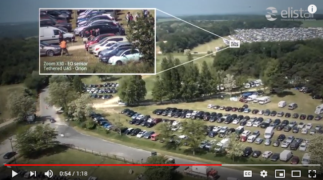
Paris–Le Bourget Airport-The Safe-T tethered drone system was utilized to perform maintenance on the airport’s Precision Approach Path Indicators (PAPI), which are blocks of four lights located beside landing runways that provide visual guidance information to pilots for acquiring and maintaining a safe and accurate glide slope on final approach. Placed perpendicular to the runway approach path, generally on the left side, each PAPI unit displays a row of lights emitting red light below a certain angle, and white light over a certain angle. Shown in the small box in Figure 5 is the teathered UAV. Shown in the larger box is its point of view and the PAPI indicator. 
Figure 6: The Point of View Screen of a Tethered UAS
In the video below is another application of the same tethered system but being utilized to inspect the gateways at CDG airport which is also in Paris France.
Video 2: A Tethered UAS Inspecting a Gateway ad CDG Airport
Huesca-Pirineos airport- In this case study, Canard Unnamed Aerial Systems are inspecting runway lights. The inspections were performed with a crew of two, a certified drone pilot and an operator. Coordination with the airport was carried out through VHF radio according to the procedures established by the airport and CANARD. In order to avoid impact on airport operations, the inspections were performed outside of the operational hours as shown in Figure 7.
Figure 7: Canard Unmanned Aerial Systems at Huesca-Pirineos Airport
The results of the inspection were obtained in real time provided to the maintenance crew. In less than 48 hours, canard was able to provide the reviewed and signed reports. Although Poland's regulations are different from U.S. FAA regulations, this case is another example of how UAS can benefit Airports.


Conclusions
Although you will likely encounter negative themed news stories when you search online keywords such as drone and airport, there are a growing number of airports embracing UAS technology. Although these case studies were from larger airports, small airports will benefit from less expensive unmanned aerial systems when flown professionally. As UAS becomes more vital to the National Airspace System, can it survive in airport applications despite occurrences of amateur operator ignorance?

Reference
Butterworth-Hayes, P. (2019, April 30). AUVSI XPONENTIAL 2019 News - AUVSI and ACI-NA set up UAS airport mitigation task force. Retrieved May 18, 2019, from https://www.unmannedairspace.info/latest-news-and-information/auvsi-xponential-2019-news-auvsi-and-aci-na-set-up-uas-airport-mitigation-task-force/

Tuesday, April 30, 2019

Lab 11 UAS Mission

Lab Description

Perhaps one of the most lengthy labs yet, this project has multiple parts and is mainly about the extensive planning and crew resource management procedures that are essential to complex unmanned aircraft systems. Specifically, myself and small group are going to learn the basic fundamentals of using the C- Astral Unmanned Aerial System. For clarity, the C-astral UAS consists of the UAV, the the ground control station, the catapult, and the parachute. Special emphasis for this lab is placed on the pre-planing of this UAS and below are the objectives that will be covered:
  • Gain a basic understanding of mission planning essentials
  • Understand how mission planning and pre-flight checks are integrated
  • Learn how to use C-Astral Mission Planning software

Table Of Contents

Part 1-----------------------------------------------------------Overview of C-Astral UAS
Part 2-----------------------------------------------------------Un-boxing the C-Astral
Part 3-----------------------------------------------------------C-Astral UAS Mission Planning
Part 4-----------------------------------------------------------Overview of the C-Astral Checklists
Part 5-----------------------------------------------------------Office Checklist
Part 6-----------------------------------------------------------Packing Checklist
Part 7-----------------------------------------------------------Pre-flight Checklist
Part 8-----------------------------------------------------------C-Astral Software
Part 9-----------------------------------------------------------C-Astral Software Demonstration
Part10----------------------------------------------------------Conclusion

Part 1: Overview of C-Astral UAS

The C-Astral Bramor UAS is a relatively complex system with nearly fully autonomous capability and offers multi-spectral, visible light, and thermal remote sensing in one package. Based out of Slovenia, this system is capable of acquiring data for surveying and provides fast and precise results. Although it can greatly outperform most fix winged UAS systems, it must carefully be operated in accordance with the United States FAA regulations.  Shown in Figure 1, is the Bramor ppX with its catapult and Ground Control Station Unit.

Taken from the C-Astral User Manuel, "the system can be safely operated by one operator/pilot in command, but a crew of two is desirable for situational awareness purposes and where regulations require so". Therefore in the Part 4, myself and a small team of other UAS students engaged in a 1-hour crew resource management activity where we went through non flight procedures only! As one of my first extensive large scale UAS checklist, there will be many more improved blog posts in future posts. 
Figure 1: C-Astral Bramor ppX and its Catapult

Part 2: Un-boxing the C-Astral

In this class, we have available a C-Astral ppx which we will be using for future missions. Shown in Figure 2, are two C-Asteral equipment cases. Case 1 has the C-Asteral UAS, its air-frame, and its and Ground Control Station. Case 2 has the catapult equipment.
Figure 2: Case 1 and Case 2
Combined together, the C-Asteral is transported with Case 1 on the top, and Case 2 on the bottom shown in Figure 3.
Figure 3:C-Astral Cases for Transportation
Shown in Figure 4, is Case 1 opened. Below Figure 4, you will see the a description of each item listed excluding the body of Bramor itself.
Figure 4: Case 1 Opened
1.Batteries 
2.Cables
3.Backup Propellers
4.Parachute
5.Septentrio GNSS Ground Control Station
6.Camera lense Cleaner
7. ADS-B-S-Mode Transponder- connects to ground control station
8.Wing Tape
9.Tools/ Documentation/Manuals
Within the lid of Case 1, a sub-compartment between the Bramor UAS a hosts the two large white wings and the two small winglets shown in Figure 5. 
Figure 5: Bramor Wings and Winglets
Referring to Case 2, is the folded catapult equipment shown in Figure 6.
Figure 6: Folded Catapult
Referring to Figure 7, is a diagram of the elastic catapult when set up taken from the the C-Asteral help manual. Below Figure 7 is a description of items that should be looked over during the pre-flight checklist. 
Figure 7: Elastic Catapult Diagram
  1. Catapult legs
  2. Safety lock
  3. Catapult Pulley
  4. Catapult Rail
  5. U shackle
  6. Elastics
  7. Winch rope
  8. Middle hinge
  9. Middle lock
  10. Rubber and Sticker
  11. Breaking rope
  12. Catapult carbon seating
  13. Trolley
  14. Trolley wheel
  15. Safety Pin
  16. Catapult release
  17. Winch handle
  18. Leg plate
  19. Winch
Part 3: C-Astral UAS Mission Planning

Within this topic, there are multiple subcategories that I could spend days working on, but since I am a college student enrolled in other classes, consider this list a skeleton of items to consider. Note, these items are in no particular order and it is up to you to determine whether or not your procedures are inclusive enough. 
  • Know your UAS- although this sounds obvious, certain UAS perform better in certain missions. To maximize the performance of a UAS, this will greatly depend on the experience of the pilot, robust pre mission planning, and how much effort you put into to knowing airspace, regulations, and weather. Shown in Figure 2, are two charts displaying the C-Astral's technical and flight parameter data. Since I know that the flight will be pre-programmed and autonomous, I have to ensure that the area I am flying in can accommodate those needs. If not, I will need to use a different UAS. Lastly, this UAS requires a parachute to land therefore one must have to know how to fold a parachute in order to not to destroy the aircraft upon a completed mission! 
    Figure 8: Technical data and flight Parameters of C-Astral UAS
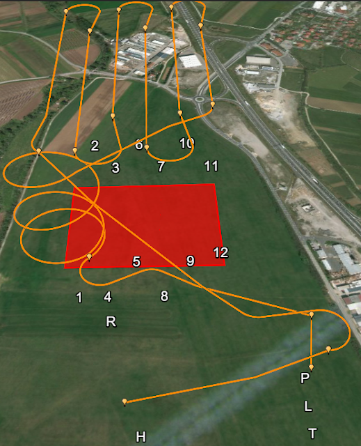
  • Know your study site- Figure 2 depicts a simulation screenshot of the C-Asteral in a field, Symbolized with a fix winged UAV Icon, the C-Asteral is in its Home position, the circle directly North of it is the Take off Icon. The triangle with the numbers are the Waypoints, the circle with the capital R is the Rally Point, the P is the Parachute Point and the L with the purple spot is the estimated Landing Point. 
    Figure 9: Study Site Icons
         Furthermore, knowing your study site can help determine places to set up items such as:
    • Ground Control Stations
    • Ground Control Points
    • Possible Obstructions
      • Tall trees
      • Buildings
      • Water
      • Power lines
    • Visual Observers
      • Amount needed to maintain situational awareness
      • Where each observer will be placed
    • Take Off points
    • Way-points
    • Landing Points
    • Emergency Landing Locations
  • Cell Signal- while in remote locations, consider who is going to have access to internet, let alone real-time weather and appropriate mobile applications such as B4UFLY, LAANC, etc.., On the other-hand, as depicted in Figure 3, signal is not always reliable. 
Figure 10: Challenges of Cell Phone Signal
  • Crowd Considerations- Unless exempted from current FAA regulations, CFR Part 107.39 operations explicitly prohibit the operation of a UAS over people who are not participating. 
  • Know the vegetation
    • Site accessibility
  • Know the Terrain
    • MSL vs AGL
  • Look at Figure 2 for possible Anthropogenic obstacles and features- although this appears as an ideal area to fly, how much walking is required to set up the UAS? Could be there be power lines on the perimeter of each road? I this area large enough for a catapult launch? Will the visual observers be challenged with varying terrain to keep eyes on the UAS at all times? These are just a few questions you should be asking yourself before you get to the field.  
  • Draw out several possible mission plans-
  • Use geospatial data available such as the data in Figure 11
  • Figure 11:Example of Available Geospatial Data
  • Check weather- The location for this hypothetical flight is near Gradisce pri Vipavi, Slovenia. Taken from google today, Figure 11 depicts the 5 day forecast. If you were to fly, which day would you choose? When determining this, do not limit yourself to just googling the weather forecast like I did. For example, for Monday although it appears that is going to rein all day, there is a significantly less chance of this likelihood at 8:00am.Some other items that you should consider when looking up weather include:
    • Daylight
    • Wind speed/wind direction
    • Visibility
    • Temperature
    • Humidity
    • Cloud Coverage
    • Real time radar
    • Dew Point
  • Equipment- In this scenario, the C-Astral Case weighs over 145 lbs and despite having handles and wheels, it cannot be carried by one person. In addition, the size of the case will make fitting it in a small car difficult so the vehicle you use to safely transport the UAS must be considered. Lastly, when you are going out in a remote area, consider the fact that there might be poor access roads to your operating site. Therefore you might have to Figure out how you are going to safely transport the system through forested areas, up steep hills, across creeks, or anywhere that cant be accessed by vehicle.  
  • Batteries Charged for all electronics- If you are going to spend hours on the field in a remote area far from adequate resources, you need to make sure that your necessary batteries are charged. The suggested items below can include but is not limited to:
    • Cell Phone
    • mifi source
    • Transmitter
    • UAV batteries
    • Ground Control System Batteries
    • Camera Batteries
    • Sensor Batteries
    • A generator

Part 4: Overview of C-Astral Checklists

In Figure, is the C-Astral Bramor ppX  Checklist handbook. Within this handbook, there are several sub checklists that myself and 3 other people went over. The specific subsections that will be covered are the Office Checklist, the Packing Checklist, and the Preflight Checklist In total, 122 steps are listed to check but not all the steps are entirely clear. To ensure that we properly understood the items we were looking over, there were about about 20 other steps that we needed to make sure we covered. As mentioned before, there is not enough time to list every step however below are the sections and the amount of steps per section that we went over to give you an idea of our process. 

Part 5: Office Checklist (Steps 1-9)

This can be within or in addition your overall mission pre-planing therefore most of this consists of taking an inventory of and checking all the items found in Steps 1-122. Nevertheless consider this a separate checklist because pre-planning can take months (depending on the mission), where as an office checklist could be within 24 hours of a flight.

In an effort to enact a mission, we assigned a pilot in command, a co-pilot, a ground a visual observer and an equipment manager. For this specific activity I was the co-pilot and my role was to oversee mission planning, and the checklist while communicating with the pilot in command. Below, in Figure 12, is a diagram I created which lists our roles for the hypothetical mission.
Figure 12: Crew Resource Management Diagram
Important items for the office checklist include but are not limited to:
  • Batteries for all electronic devices
  • SD card
  • Tools
  • Elevation map
  • Ensuring that your case is free from damage and open/locks correctly

Part 6: Packing Checklist (Steps 9-34)

This consists of making sure that each item within both cases are carefully looked at. Important items for the packing checklist are broken down by case number include but are not limited to:
  • Case 1
    • Wings
    • Winglets
    • Parachutes
    • The parachute folding tool
    • Parachute safety pin
    • parachute hatch
    • propellers
    • Ground control station
    • electrical tape
    • Tablet
    • tablet charger
    • wing joiners
    • Mairframe hatch
    • Pitot Cover
    • USB Key
    • Appropriate chargers
  • Case 2
    • Catapult
    • Elastics

Part 7: Pre-flight Checklist (Steps 34-122)

Within this section nearly 30 of the steps involved setting up the catapult as seen in Figure 13 . Notice the of size of the catapult with respect to the equipment manager, our professor and the visual observer. Since out field demonstration didn' involving any flying, we were able to set up the UAS right in front of KLAF airport.
Figure 13: Setting up the Catapult
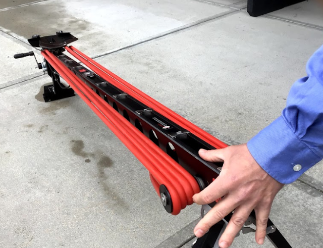
Something that confused us during the process was having to carefully stretch the bungees shown in Figure 14.
Figure 14: Securing the Bungees of the Catapult
Since the C-Astral requires a headwind, we took note of the direction based off the flag shown in the red circle within Figure 15.
Figure 15: The Catapult facing the Headwind
For learning purposes, the professor demonstrated what not to do such as holding the catapult in a way where you could get your hand cut off shown in Figure 16
Figure 16: What not to do when holding a Catapult
In the following Figure 17 is a demonstration of how to properly hold the catapult.
Figure 17: How to Properly Hold the Catapult
While the equipment manager and the visual observer set up the catapult, myself and the pilot in command began programming the C-Astral for a hypothetical mission shown in Figure
Figure 18: Setting up the Hypothetical Mission on the Ground Control Station Tablet
As a team we focused on specific items shown shown in Figures 19-22, Within each image were about 10 steps that we checked. In Figure 19, is the airframe assembled to the catapult.
Figure 19: Assembling the Airframe to the Catapult
In Figure 20, the visual observer attaches the flexible propeller to the back of the aircraft while overseen by the equipment manager.
Figure 20: Attaching the Propeller to the Bramor
Shown in Figure 21, special attention must be paid to the pitot static tube because any malfunction in this instrument will cause an in flight failure. The most common in flight failure of the C-Astral Bramor is due to a dysfunctional pitot static system.
Figure 21: Pitot Static Tube
Shown in the video below, special attention was made on properly packing the parachute. Although the video does not do it justice, I will make a step by step tutorial on properly packing a parachute in the future.
Video: Parachute Installation
Lastly, this is that a hypothetical launch would look like if the crew were to actively engage in a mission. In the future we will do so, but for now we are learning more about how to safely operate the system.
Figure 22: Hypothetical Launch of Bramor UAS

Part 8: C-Asteral Software

In Figure 23, is a screenshot of the home screen at a hypothetical field in Bosnia. Below is a description of each of the items in the  numbered boxes. 
Figure 23: Screenshot wirh Labled Boxes
Box 1
  • The Help Section-Indicated by the ?  click (on) this and it will open up an entire subsection that you can refer to for questions you may have as shown in Figure 24
    Figure: 24: The Help Section Window
  • The Map Icon-Changes the map so that you can see other items such as cities, rivers, and other topography more clearly
  • The Attitude Indicator-a flight instrument that informs the pilot of the aircraft orientation relative to Earth's horizon, and gives an immediate indication of the smallest orientation change
     Box 2
    • Battery Life, Communications, the Global Navigation Satellite System Receiver gauges
    • Altitude Above Ground Level, Airspeed inidcatior, Climb, Throttle gauges
    • Wind 
    • The Connection Status-Indicates when the Bramor is connected to the ground control station
    • Simulation Status
    Box 3
    • Click (on) Settings indicated by the gear icon and a small window will appear shown in Figure 26
      Figure 26: Settings Window
    • Minimize, expand and close buttons are next to the settings button
    • Metadata showing the elevation, distance duration etc.., is below the buttons
    Box 4
    • Safe mode
    • Manual mode
    • Take off mode
    Box 5
    • Map- Click (on) this to enable different features for mission options shown in Figure 27
      Figure 27: Mission Options
    • Mission Settings- when clicked on Figure 28, a window similar to Figure will appear. In this scenario altitude is set to 200m which would not work in a current part 107 operation. Nevertheless, speed is critical to the aircraft's flight, and overlap and sidelap are crucial for photogrammetry. 
      Figure 28: Mission Settings
    • Draw- when clicked on, a window similar to Figure 29 will appear. This is how you create a flight path and waypoints. 
      Figure 29: Draw tool
    • Hide, delete, clear, and undo/redo buttons all help edit waypoints
    Box 6
    • Sensor Calibration
    • Waypoint Upload
    • Parachute Pop
    Box 7
    • Upload mission indicated by the folder
    • Waypoint status- Click (on) the arrow like icon and a chart similar to Figure 30 will appear
      Figure 30: Waypoint Chart
    • Save Icon, saves the mission
    Box 8
    • Camera Controls
    • View/Edit Photos
    • Auto Camera
    • Zoom

    Part 9: C-Astral Software Demonstration

    In this section, I have completed simulated missions for three locations. Location 1, the Bramor test site shown in Figure 31 . Location 2. the County Amphitheatre Park in West Lafayette shown in Figure 33  , and Location 3, the Thorton Quarry Shown in Figure 35 .

    Figure 31: Location 1
    Throughout this demonstration, was tasked with addressing the following:
    • Experiment with  altitudes, as well as relative and absolute heights
    • Take note at how mission orientation relates to terrain issues
    • Draw a corridor mission along a linear feature such as a road in the vicinity
    Similar to Figure 28, I changed  the speed and the altitude at the highest settings to see that kind of overlap would occur. In Figure 32, is an overhead view of the the first simulated mission. Below it are some items that help us understand what the Bramor did. The simulated mission was successful.

    Figure 32: Aerial View of Flight Path for Location 1
    Within the purple box is the area that the Bramor covered
    • The clear boxes within the purple box are the photos the Bramor captured
    • The orange diagonal lines are the flight path to the way points
    • At the moment of this screenshot, the Bramor was heading to waypoint 8 
    In Figure 33, is the 3D view of Location 1 and its flight path. Below Figure 32 are more items of importance.
    Figure 33: 3D View of Flight Path for Location 1
    • H stands for home
    • R stands for rally point
    • P stands for parachute deployment Point
    • L stands for Loiter
    • The numbers are the order the Bramor flew in
    • The Red box is the area the Bramor covered
    Location 2

    As you can see in Figure 34, there is significantly more planning that needs to be done compared to Location 1. For example, is the field north of the amphitheater large enough to serve as the Bramor's home position. In addition, are the trees too tall for an altitude of 50 meters? Lastly, if our mission is to gather adequate photos of the amphitheater parking lot, what ideal altitude can we fly at in accordance with FAA Part 107? With a set altitude of 50 meters, the mission flew successfully, but would this flight path be safe in real life?
    Figure 34: Satellite View of Amphitheater Parling lot
    In Figure 35, is a comparison of the 3D flight path vs the 2D flight path from above. Notice how much more tight and complex this mission was compared to the mission on the test site.
    Figure 35: 2D vs 3D Flight Path Comparisons for Location 2

    Location 3


    Perhaps the most changeling of the locations is Thorton Quarry located in Illinois. Shown in the satellite image in Figure 36, there are multiple elevation differences, roads, and a neighborhood in the bottom right hand corner.
    Figure 35: Thorton Quarry Satellite Image
    Shown in Figure 37 was my first flight path draft. Notice all the elevation hazards in orange circles. If the UAS were to fly here, it would crash. For this mission, I  also flew it on the side of the road shown on the left. In  the left side of Figure 37, is the corrected flight with an adjusted altitude of 100 meters, notice how much farther from the road the Bramor had to be in order to safely fly.
    Figure 37: Flight Draft That would Result in Accident
    Shown in the left side of Figure 38 , is the overhead view of the Bramour on its flight successfully surveying the Quary. Shown on the right side is its 3D model.
    Figure 38: 2D vs 3D Flight Path Comparisons for Location 3

    Part 10: Conclusion

    As stated before, since the Bramor is autonomous the second you release it from the catapult, this UAS platform can require extensive preplanning in order to ensure a safe and efficient mission. Although every aspect of preplanning is important, the pre-flight check is perhaps the most important because crew resource management determines whether or not the Bramor will produce stunning cost effective deliverables, or a stunning expensive hole in the ground. Although people are complacent with fallowing the traditional checklists that are given to them, professionals that want to minimize the likelihood of an accident will often add extra more specific steps in order to ensure that everyone is aware of themselves, the UAS system, the mission, and the environment.

    More importantly, as demonstrated by these simulations, UAS missions can vary tremendously. Therefore, having a constant awareness for safety and being able to address potential hazards early could save you a UAV, a lawsuit, or even a life in the long run. In future labs, you will see more demonstrations of the Bramor ppX and how we will operate it as professionals in the field. As UAS relates to the client, the operator, and the national Airspace System, imagine having both the opportunity and responsibility to manage all three aspects let alone the the aircraft and all of its components.